
Through Bore Slip Ring Selection Guide for OEM Engineers
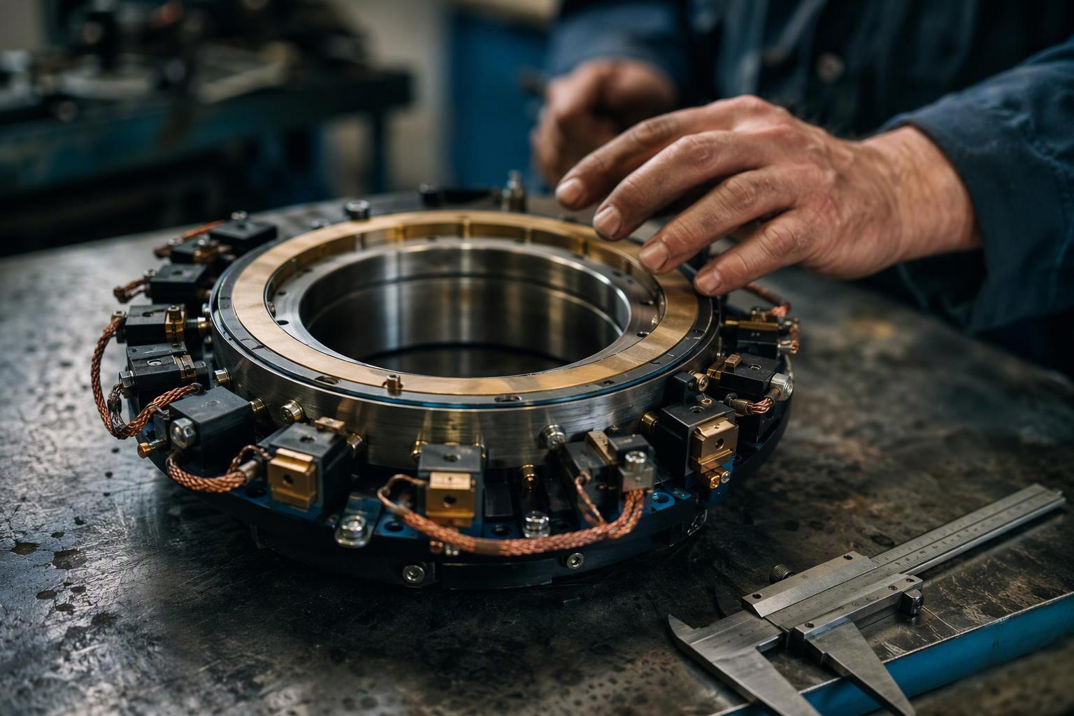
Through bore slip ring selection starts with the mechanical envelope, not the bore diameter. A through bore slip ring carries power and data across a rotating interface "while allowing a continuous hole (or bore) through the center", so shafts, fluid lines and optical channels can pass through the assembly (Servotecnica, 2025-09-30). That single feature drives every downstream decision: bore and shaft fit, outer diameter, axial length, cable exit, circuit count and signal type.
This slip ring selection guide is built for OEM engineers who need an evaluation framework rather than a catalogue. It works through the envelope, the electrical specification, the communication interface, the duty and environment, the integration requirements, the standard-versus-custom decision and the supplier evaluation, then closes with the information a complete RFQ should carry.
Introduction: How Should OEM Engineers Select a Through Bore Slip Ring?
Select a through bore slip ring by fixing the mechanical envelope first, then the electrical and communication requirements, then the duty and environmental conditions, and only then the supplier and the standard-or-custom route. Each step constrains the next: a bore chosen from a nominal shaft diameter can fail at assembly, and a circuit count chosen before the current profile is known can force a larger housing later.
The framework below treats every rating as something to be confirmed against a supplier's published documentation or a named standard. Where the published evidence stops, the guide says so and turns the gap into an RFQ question.
Key Takeaways
Specify the bore as a tolerance class against a shaft class, never as a nominal diameter; ISO 286 defines clearance, transition and interference fits, and clearance is computed from diameter limits.
Separate continuous current from inrush and peak current in the RFQ, and request a current-versus-ambient curve for the actual mounting, because published ratings are stated at defined conditions.
Treat electrical continuity as necessary but not sufficient for Ethernet and fieldbus: insertion loss, return loss, crosstalk and impedance discontinuity govern signal quality.
Read an IP rating as a test-based claim about the enclosure under IEC 60529, not as a guarantee of corrosion, condensation or impact resistance.
Follow the supplier's installation sequence, keep the anti-rotation tab free to move, and never let the slip ring carry the weight of connected equipment.
Put the mechanical envelope, electrical profile, communication interface, environment and acceptance criteria into one RFQ package.
What Is a Through Bore Slip Ring and When Should OEM Engineers Choose One?
A through bore slip ring is a rotary electrical interface with a central opening that lets a shaft, fluid line or optical path pass through the rotation point while power and signals cross from a stationary structure to a rotating one. It suits an application only when the mechanical envelope, the circuit count, the communication performance and the operating conditions all line up. The bore is the reason to pick this family, not a bonus feature.
Through-bore designs "center around a hollow shaft construction", with conductive rings mounted around the bore, unlike "traditional capsule slip rings that feature a closed housing"; the opening exists so hydraulic lines, pneumatic channels or drive shafts can pass through the centre (Servotecnica through-bore guide, 2025-09-30). That hollow shaft slip ring geometry is what distinguishes the family from every enclosed alternative.
How Through Bore Slip Rings Work
A rotor assembly carrying the conductive rings turns with the machine shaft, while the brush block stays fixed to the stator housing, and sliding contact between brush and ring carries current across the rotating interface. The central opening is a mechanical feature only: it gives the shaft or service line a clear axial path and does not add load capacity. A slip ring does not replace structural bearings or other support components, so the machine structure must still locate and carry the rotating assembly.
Typical OEM Applications
The requirement pattern repeats across machine types: a rotating joint that must pass a shaft, a fluid line or an optical path while carrying power and data. Rotary indexing tables need a clear centre for tooling actuation. Packaging machinery with carousels routes pneumatic lines through the bore. Industrial automation and robot axes pass actuator or gear shafts through the rotation point. Rotating inspection platforms and shaft-mounted production machinery need electrical continuity without a cable wrap. These are engineering requirement patterns, not reference installations.
Through Bore vs Capsule vs Separate Slip Rings
Criterion | Through bore | Capsule | Separate |
|---|---|---|---|
Mechanical configuration | Rings around a hollow shaft | Closed housing | Rotor and stator as separate parts |
Central opening | Continuous bore | None | None |
Installation approach | Shaft-mounted or flange-mounted | Compact enclosed unit | Customer-defined arrangement |
Space requirements | Bore and outer diameter drive the envelope | Outer diameter and length drive it | Rotor-stator spacing and alignment drive it |
Typical applications | Shaft, fluid or optical path through the joint | Closed pocket with limited room | Geometry that demands a split design |
Main limitations | Concentricity and anti-rotation must be managed | No axial passage | Highest integration effort |
The comparison is structural, not a ranking. Each family solves a different mechanical problem, and the choice follows from whether the machine needs a clear centre.
How Do You Select the Correct Bore Diameter and Mechanical Envelope?
Select the bore from a specified fit, not from the nominal shaft diameter. A hollow-component drawing should call out a bore tolerance class against a shaft class, for example Ø25 H7 with Ø25 h6 or g6, and clearance is then computed from the diameter limits rather than the nominal size (Premsa Industries fit reference, undated). ISO 286-1 defines a clearance fit as one that always provides clearance, with the hole's lower limit equal to or larger than the shaft's upper limit, and ISO 286-2 tabulates the limit deviations for nominal sizes (ISO 286-1:2010, 2010).
The practical consequence is that a bore matched to a nominal shaft can be tight on assembly or loose enough to lose concentricity. H7/g6 is described as the precision sliding fit and the de facto standard for accurate location, while H7/h6 is a locational clearance where parts stay put but assemble by hand; IT7 at 25 mm spans 21 µm (Premsa Industries fit reference, undated). Treat that pairing as an engineering analogy for the bore-to-shaft interface, because the slip-ring supplier's drawing, not the fit table, sets the contractual limit.
Shaft Diameter, Bore Clearance, and Mechanical Fit
Distinguish the shaft diameter, the bore diameter and the clearance between them, and check the adjacent components that share the same shaft.
Outer Diameter, Axial Length, and Cable Routing
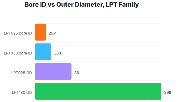
The wall between bore and outer diameter therefore stays in a similar band across the series, so a larger bore costs radial space. Axial length is fixed by the outline drawing for the chosen circuit configuration, and the rotor and stator cable exits must be planned before the envelope is frozen, because the leads need room to route without being pulled.
Comparing JINPAT LPT Series Configurations
The through bore slip ring range gives the family view, the LPT038 published specifications show a Φ38.1 mm bore with 300 mm stator and rotor leads, and the LPT050 dimensional drawing is the document that fixes the axial envelope. Read ratings from the table or datasheet for the specific model, never from the model name.
How Should OEM Engineers Specify Voltage, Current, and Circuit Configuration?
Electrical selection starts with three numbers, not one: operating voltage, continuous and intermittent current per circuit, and the count of independent circuits. Circuit allocation, electrical loading, thermal conditions and the mechanical envelope have to be settled together, because a rating declared for one set of conditions does not transfer to another.
Define Voltage, Current, and Circuit Quantities
List each quantity separately on the specification sheet. Record the system voltage and any transient overvoltage, then split current into continuous and peak rather than quoting a single figure. Count circuits by function: power, signal, encoder, bus and spare. The LPT025 datasheet declares 6 circuits at 6×5 A, 240 VAC/DC, insulation resistance ≥500 MΩ at 500 VDC, dielectric strength 1000 VAC at 50 Hz, 0 to 300 rpm, a Φ25.4 mm inner diameter, precious-metal contacts, an aluminium alloy housing, −20 °C to +60 °C and ≤60 %RH (the LPT025 datasheet, undated). Those are the conditions under which the rating is declared, and the application has to be checked against them.
Evaluate Current Capacity Under Operating Conditions
A continuous rating applied to a load with motor inrush or servo acceleration is the most common electrical error in slip-ring selection. Duty type governs how a load is declared, and IEC 60034-1 is the rating-and-performance standard whose duty-type framing (S1 continuous, S2 short-time and so on) is used for that declaration; edition 15.0 was published in 2026, superseding edition 14.0 of 2022 (IEC 60034-1 Ed. 15.0:2026 listing, 2026). No universal derating formula applies to slip rings: derating depends on ambient temperature, mounting, cooling and duty, so the RFQ should request a current-versus-ambient curve for the actual installation.
Mixed Power and Signal Requirements
Mixed builds are standard practice rather than a special order. The LPT038 dimensions and ratings show 15 A versions in 6, 12, 18 and 24-ring configurations across 4 housing lengths, with the same electrical block as the LPT025 (the LPT038 datasheet, undated). Circuit count and current are traded in fixed steps, so state the required count per current class rather than a single total, allocate power and signal to separate circuits, and state the isolation expected between them.
Electrical Specification Table
Parameter | Application requirement | Engineering consideration | RFQ information |
|---|---|---|---|
Voltage | System voltage and any transient overvoltage | Compare with the declared rating voltage, for example 240 VAC/DC on the LPT025 | Rated voltage, insulation resistance and dielectric strength required |
Continuous current | Steady-state current per circuit at the stated ambient | Declared per circuit at defined conditions | Current per circuit, ambient temperature, mounting and cooling |
Peak current | Inrush or acceleration current and its duration | Not covered by a continuous rating | Peak value, duration, repetition period and duty type |
Circuit count | Power, signal, encoder and bus circuits counted separately | Available in fixed steps such as 6, 12, 18 and 24 | Count per current class and per signal type |
Signal types | Serial, encoder, sensor, Ethernet or fieldbus | Standard and custom signal support differ by model | Protocol, data rate and channel count |
Cable requirements | Lead length, routing and connector type at both ends | Lead length is fixed per model, for example 300 mm stator and rotor on the LPT038 | Required lead length, exit direction and termination |
Pro Tip: Separate continuous from peak or inrush current in the RFQ, with the duration and repetition period of each peak. A supplier who sees only one current figure will size the circuits to it.
Can Through Bore Slip Rings Transmit Ethernet and Industrial Communication Signals?
Yes, through bore slip rings are published with Ethernet capability, but continuity does not establish protocol compatibility. The Ethernet through-bore table lists "100M ✔ / 1G ✔" per row for the LPT025, LPT038 and LPT050 builds, with 1 or 2 Ethernet channels combined with 6 or 12 power or signal circuits at 5 A per signal circuit, 10 A or 15 A (JINPAT's Ethernet through-bore table, undated). The same page's feature text mentions 10 Gbps, but no 10G row appears in the through-bore table, so a 10G requirement has to be confirmed for the specific model rather than assumed from the series.
Identify the Communication Interface
Name the protocol and the physical layer before choosing a model. EtherNet/IP "uses standard IEEE 802.3 technology at the Physical and Data Link Layers", and CAT 5E or later is recommended for reliability in manufacturing, with shielded or unshielded twisted pair and fibre all permitted (ODVA, CIP on Ethernet Technology, 2024). EtherCAT "makes use of physical layers of Ethernet and the Ethernet frame", with cable runs up to 100 m in 100BASE-TX mode and fibre for longer distances (EtherCAT Technology Group, undated). The Ethernet slip ring configurations page shows how channel count and power circuits combine in published builds.
Signal Integrity, Shielding, and Grounding
Inserting a slip ring into an Ethernet line affects insertion loss, return loss, crosstalk and impedance, and the more significant effect is the impedance discontinuity's impact on transmission-line quality and deterministic jitter; 1000BASE-T uses all four pairs with nominal 100 Ω impedance, against two pairs for 10/100BASE (Moog, When Ethernet Rotates, undated). That is why insertion loss and return loss matter more than DC resistance. Treat that as the supplier's stated claim and validate at application level with the slip ring testing checklist.
When Alternative Rotary Transmission Technologies May Be Needed
When the data rate, channel count or electromagnetic environment exceeds what a contacting ring can carry, optical rotary transmission becomes the alternative. The distinction is physical: the fieldbus and Ethernet pages describe electrical transmission over shielded conductors, while the through-bore definition explicitly allows optical channels to pass through the bore (Servotecnica through-bore guide, 2025-09-30). Where the bore is used for a fibre path, the electrical ring and the optical joint are separate transmission problems to be specified separately.
How Do Speed, Duty Cycle, and Environmental Conditions Affect Selection?
Speed, duty cycle and environment set the operating envelope in which the electrical ratings remain valid. The published LPT family is rated at 300 rpm, and the LPT025 and LPT038 datasheets state a working speed of 0 to 300 rpm, a working temperature of −20 °C to +60 °C and working humidity ≤60 %RH (the LPT025 datasheet, undated; the LPT038 datasheet, undated). An application outside those conditions is a customization question, not a margin to be absorbed silently.
Rotational Speed and Duty Cycle
Distinguish normal operating speed from maximum speed, and continuous rotation from start-stop duty. Duty cycle affects thermal behaviour and brush wear, and the duty-type framing in IEC 60034-1 is the vocabulary for declaring it (IEC 60034-1 Ed. 15.0:2026 listing, 2026).
Temperature and Environmental Protection
The IP code as defined in IEC 60529 classifies the enclosure's protection against access to hazardous parts, against ingress of solid foreign objects and against harmful water ingress, for equipment rated up to 72.5 kV, and it explicitly does not cover mechanical impacts, corrosion, solvents, fungus, vermin, solar radiation, icing, condensation moisture or explosive atmospheres (ANSI/IEC 60529-2020, 2020). An IP65 claim therefore says nothing about IP67 behaviour, and an IPX8 rating is meaningful only with the agreed depth and duration written into the RFQ.
Service Life and Maintenance Planning
Plan maintenance from the wear mechanism and the duty, not from a universal figure. The LPT025 datasheet states that fibre brushes do not require lubrication and produce virtually no wear debris, for maintenance-free operation (the LPT025 datasheet, undated), but no published hours or revolutions figure accompanies the through-bore range. Request the life-test basis and the maintenance interval for the actual duty in the RFQ, and use the slip ring service life expectations to structure the question.
What Mechanical Integration Requirements Should OEM Engineers Review?
Review the installation sequence, the anti-rotation arrangement, the cable routing and the load path before the envelope is frozen. JINPAT's through-bore installation guide sets the order: arrange the rotor and stator wires first, stabilise the slip ring on the rotating shaft, adjust the shaft and mounting-hole position, fasten the rotor side with 4 screws, ensure concentricity before fixing the screws, insert the poke rod in the U slot of the anti-rotation tab, and arrange wires to avoid twining with the rotor (JINPAT's through-bore installation guide, undated).
Mounting Alignment and Rotor-Stator Restraint
The anti-rotation tab needs play, not a hard clamp. The installation instruction states "do not fix anti-rotating pin forcibly, or it would affect life time of slip ring", and for fluid slip rings a certain freedom must be kept at the stator connection or the ring can be damaged (Moflon installation instruction, undated). Suppliers publish concentricity limits in the order of 0.1 mm for compact units, but for through-hole series the published requirement is procedural rather than a numeric runout value (Motion Control Products catalogue, 2026). A circular run-out callout to a datum, as defined in ISO 1101:2017, is how the requirement becomes contractual (ISO 1101:2017, 2017); the limit itself must come from the supplier's drawing.
Cable Routing and Mechanical Protection
The precautions list is specific: the slip ring cannot bear the weight of its connected equipment, wires should be free from extra pull and weight, wire insulation must stay intact, a flexible connection should replace a rigid one between rotor and stator to ensure longer life, screws need locking measures against vibration, and harsh environments need protection measures or a higher protection level (the LPT precautions list, undated). Each of those points is a drawing and routing task, not an installation afterthought.
Review the Complete Rotating Assembly
Check the slip ring as one element of the rotating assembly: the bearings that carry the load, the shaft that passes through the bore, the fluid or optical path through the centre, the cable exits on both sides and the service access for inspection. The through-bore definition allows shafts, fluid lines and optical channels through the bore (Servotecnica through-bore guide, 2025-09-30), so the assembly review has to confirm that nothing passing through the centre loads the ring.
Standard vs Custom Through Bore Slip Rings: Which Should an OEM Choose?
Choose a standard configuration when the application fits the published envelope and ratings, and go custom when a requirement falls outside them. The published LPT range covers bore sizes, circuits, current ratings, and voltage ratings (JINPAT LPT through-bore table, undated). A requirement inside that grid is a standard selection; a requirement outside it is a customization discussion.
When to Choose a Standard Configuration
The same page directs other signal types, including Ethernet, USB, HDMI, SDI, LVDS and fieldbus, to a direct enquiry, which marks the boundary between the standard catalogue and the engineered build.
When Customization Is Appropriate
Customization is appropriate when a stated parameter falls outside the standard grid. The supplier's stated customization parameters are current capacity, through bore size, circuit configuration, environmental protection level and installation requirements (the high-current offshore announcement, 2026-05-19). Each of those is a design variable with a cost and a lead time, so the RFQ should say which parameter is fixed by the machine and which can move.
Standard vs Custom Selection Matrix
Requirement | Standard configuration | Custom configuration |
|---|---|---|
Bore and outer diameter | Inside the published Φ12.7 to Φ180 mm bore range | Outside the range, or a non-standard envelope |
Circuit count and current | 6 to 24 circuits at 5 A per signal circuit, 10 A or 15 A | Mixed current classes or counts outside the steps |
Voltage | 240 VAC/DC, with 380 VAC/DC listed for LPT025 and LPT038 | Higher or application-specific voltage |
Speed | 300 rpm rated | Above the rated speed |
Signal type | Serial, RTD, thermocouple, sensor and encoder signals on standard models | Ethernet, USB, HDMI, SDI, LVDS and fieldbus by enquiry |
Environmental protection | Published IP range per model row | A specific protection level tied to a test method |
Installation | Standard shaft or flange mounting | Application-specific mounting or installation requirements |
The custom-vs-standard checklist is a useful cross-check before committing to either route.
How Can OEM Engineers Evaluate Through Bore Slip Ring Suppliers?
Evaluate a supplier on the documentation it will release, the acceptance criteria it will agree and the lifecycle support it can evidence. The published certification block lists ISO 9001:2015, ISO 14001, a CE marking certificate for the LPTS series through-bore slip rings, a UL certificate, Bureau Veritas marine type approval, RoHS 2.0 compliance, REACH with an SGS SVHC report, FCC certification and an explosion-proof certificate, with 96 patent applications, 89 authorised, as of March 2026 (JINPAT's published certifications, 2026-03). Certificates establish a management system and conformity route; they do not replace the model-specific datasheet.
Required Technical Documentation
Ask for the datasheet for the exact model, the outline drawing with the axial envelope, the bore and shaft fit callout, the wiring schedule, the current-versus-ambient information for the mounting, and the installation instructions. The published LPT pages show the pattern: a specification block with circuits, voltage, dielectric strength, insulation resistance, speed, bore, contact and housing material, temperature and humidity, plus outline drawings per model variant (the LPT025 datasheet, undated). A quotation that gives only a model name leaves the engineer to infer the ratings.
Application-Specific Acceptance Criteria
Agree the acceptance test before the order: continuity and insulation resistance per circuit, dielectric strength, and for communication builds the signal test that matches the protocol. The acceptance criteria should name the measurement, the limit and the test method.
Procurement and Lifecycle Considerations
Confirm the certificate set that applies to the destination market, the spare-part and repair route, and the documentation that ships with each unit.
How we apply this at JINPAT, the publisher of this guide: we develop application-specific slip rings against the current, voltage, circuits, communication protocols, installation dimensions, rotational speed and environmental conditions a customer states. We do not set your acceptance criteria or verify your envelope; you still define the tests and sign off the documentation, with any supplier, ours included.
What Information Should Be Included in a Through Bore Slip Ring RFQ?
A complete RFQ states the mechanical envelope, the electrical profile, the communication interface, the environment and the project constraints, each with the condition under which it applies. The supplier's own customization parameters, current capacity, through bore size, circuit configuration, environmental protection and installation requirements (the high-current offshore announcement, 2026-05-19), map directly onto the sections below.
Mechanical and Operating Requirements
State the shaft diameter with its tolerance class, the required bore fit, the available outer diameter and axial length, the mounting style, the cable exit directions, the rotational speed and the duty cycle.
Electrical and Communication Requirements
State the voltage, the continuous current per circuit, the peak current with its duration and repetition, the circuit count by function, and the signal types with their protocols and data rates.
Environmental and Project Requirements
State the ambient temperature range, the humidity, the presence of dust, water, condensation or corrosive media, the required IP rating with the test condition, and any certification the destination market requires. Because IEC 60529 classifies the enclosure only and excludes corrosion, condensation and impact (ANSI/IEC 60529-2020, 2020), the RFQ should describe the environment as well as the rating.
Through Bore Slip Ring RFQ Checklist
Item | What to state |
|---|---|
Shaft and bore | Shaft diameter with tolerance class, required bore fit, run-out requirement and datum |
Envelope | Available outer diameter, axial length, mounting style and cable exit directions |
Rotation | Normal and maximum speed, duty cycle and duty type |
Power circuits | Voltage, continuous current per circuit, peak current with duration and repetition |
Signal circuits | Count by function, protocol, data rate and channel count |
Environment | Ambient temperature, humidity, dust, water, condensation, corrosive media and required IP rating with test condition |
Certification | Market-specific certificates and the validity date required |
Acceptance | Test methods, limits and the documentation to ship with each unit |
Lifecycle | Expected service interval, maintenance access and spare-part route |
The specification checklist gives a fuller field list to work through before the RFQ is issued.
Frequently Asked Questions About Through Bore Slip Ring Selection
How Much Clearance Is Needed Between the Shaft and the Through Bore Slip Ring?
The clearance is set by the specified fit, not by a single universal number. A bore callout such as Ø25 H7 against a Ø25 g6 shaft gives a clearance fit computed from the diameter limits, and at 25 mm the H7/g6 pairing yields a clearance range of about +0.007 to +0.041 mm (Premsa Industries fit reference, undated). Confirm the limit on the supplier's drawing, because the slip ring's bore tolerance governs the assembly.
Can Power and Ethernet Signals Be Combined in One Through Bore Slip Ring?
The combination has to be validated at application level, because insertion loss, return loss, crosstalk and impedance discontinuity affect signal quality even when continuity is good (Moog, When Ethernet Rotates, undated).
Does a Larger Bore Diameter Mean Higher Current Capacity?
No. A larger bore increases the radial envelope, with a Φ180 mm bore in a Φ298 mm body, and does not by itself raise the current rating.
Can a Through Bore Slip Ring Operate Continuously?
The published LPT models are rated for continuous rotation at up to 300 rpm, with the LPT025 and LPT038 datasheets stating a working speed of 0 to 300 rpm and a working temperature of −20 °C to +60 °C (the LPT025 datasheet, undated). Continuous operation within those conditions is the declared use; operation outside them, including higher speed or ambient, is a customization question.
What Should an OEM Do if a Standard LPT Model Does Not Match the Application?
Move to a customization discussion and state which parameter falls outside the published grid. The supplier lists current capacity, through bore size, circuit configuration, environmental protection and installation requirements as customization parameters (the high-current offshore announcement, 2026-05-19), so the RFQ should identify the fixed requirement and the acceptable range for everything else.
Conclusion: Select a Through Bore Slip Ring Based on the Complete Application
The selection holds together only when the envelope, the electrical profile, the communication interface, the duty and the environment are specified as one package. The bore is a fit against a shaft class, not a nominal diameter; the current rating is declared at defined conditions and must be checked against inrush and duty; Ethernet and fieldbus capability is a physical-layer question, not a continuity question; and the IP rating is a test-based claim about the enclosure under IEC 60529 (ANSI/IEC 60529-2020, 2020). Where the published evidence stops, the gap becomes an RFQ question rather than an assumption.
Next Steps for OEM Engineering Teams
Assemble the drawing set and the operating data, then send your specification and drawing set for technical review. The review should confirm the bore fit and run-out requirement, the current profile against the declared conditions, the communication interface against the published rows, the environmental protection against the test condition, and the acceptance criteria before any order is placed.
Name
Email*
*Phone
Application
Message
*
