
High Current Slip Ring Thermal and Electrical Design Guide for OEM Engineers

Introduction
High-current slip rings fail thermally far more often than they fail electrically. A ring and brush set that carries the load on the bench can still overheat in service once ambient temperature, enclosure, duty cycle and contamination are added, and the resulting film breakdown or brush damage is rarely reversible. This guide is written for UK and EU OEM engineers designing slip rings into heavy machinery and marine equipment, where long duty cycles and harsh environments leave little thermal margin.
It covers four connected tasks: sizing the ring to the real current profile rather than a nameplate figure, setting a defensible allowable temperature rise, designing the ring–brush contact so current shares predictably, and estimating the losses that drive temperature. It then addresses cooling and environmental protection, and closes with monitoring, UK/EU compliance and validation testing.
The method is deliberately two-stage. Calculate first — current density, contact drop, I²R, friction — to choose a configuration with margin. Then test to thermal equilibrium, because calculated losses cannot capture film behaviour, airflow in a real enclosure or the self-reinforcing imbalance between parallel brushes. Where a number depends on the application, this guide says so rather than inventing a value; confirm such figures against supplier documentation and the applicable standard.
Key takeaways
Size for the worst sustained and peak current the machine will actually see, not the nominal rating.
Treat temperature rise as a design budget measured against coolant temperature, and keep a thermal margin to the insulation class.
Contact voltage drop, not ring resistance, usually dominates electrical loss at high current.
Parallel brushes share current unevenly, and the imbalance can reinforce itself into failure.
Validate at thermal equilibrium under worst-case ambient, speed and load before releasing the design.
Duty and sizing fundamentals
Sizing a high-current slip ring means converting the machine's real operating profile into a current, a duty class and a temperature-rise budget before any hardware is chosen. The three decisions below are interdependent: continuous duty at high ambient removes margin that intermittent duty would preserve, and a derated ring may need more parallel paths or a larger ring diameter to stay within its limits.
Define current categories and duty
Start by separating the currents the ring will carry into categories, because each stresses the contact differently. Typical categories are continuous rated current, short-time overload, starting or inrush current, and fault current. A crane hoist, a thruster drive and a drilling top drive each present a different mix, and the ring must be sized for the sustained thermal load plus the peaks that recur often enough to heat the contact.
Duty class matters as much as magnitude. IEC 60034-1 assigns duty types (S1 continuous, S2 short-time, S3 intermittent periodic and so on) and places the responsibility for declaring duty on the purchaser, so the OEM should state the cycle explicitly rather than leave the supplier to assume continuous full load. For a slip ring, the practical question is the thermal time constant of the ring and brush assembly against the length of the load period: a peak shorter than the assembly's thermal time constant contributes less to steady temperature than its magnitude suggests, while a repeated peak with a short rest interval can accumulate.
A worked example makes the distinction concrete. Suppose a marine winch draws 600 A continuously during hoisting, 900 A for 30 s during acceleration, and 150 A while lowering. The continuous 600 A sets the steady-state thermal design; the 900 A peak sets the contact and brush-current-density check; the 150 A period determines whether the ring cools between cycles. Sizing on the 900 A peak alone would oversize the ring; sizing on an averaged current alone would understate the peak contact stress. Record both, with their durations and repetition, in the specification sent to the supplier.
Set allowable temperature rise limits
An allowable temperature rise is the permitted difference between a part's measured temperature and the coolant temperature, and it must be set below the limit that would degrade the insulation system or the contact film. IEC 60034-1 defines temperature rise this way — the difference between the part's temperature and the coolant temperature measured per the standard — and tabulates limits by machine part and insulation class.
The insulation class sets the ceiling. IEC 60085 classifies insulation systems by thermal endurance, and the commonly cited class temperatures are 130 °C for class B, 155 °C for class F and 180 °C for class H, each associated with a nominal 20 000 h life expectancy at that temperature. Temperature-rise classes in IEC 60034-1 are stated in kelvin: class B at 80 K, class F at 105 K and class H at 125 K by the resistance method. The thermal margin is the insulation class temperature minus the sum of temperature rise and ambient — for example, class H insulation with a class F rise at 40 °C ambient gives 180 − (105 + 40) = 35 K of margin.
That margin is not decorative. The Arrhenius-based rule of 10 approximates that reducing operating temperature by 10 °C doubles insulation life, so a design that runs close to its class temperature trades life for compactness. For a slip ring, set the allowable rise so that the hottest expected spot — usually the brush face and the ring surface under the brush — stays within the class limit with margin for ambient variation and contamination. State the ambient and coolant temperature the rise is referenced to, because a rise figure without its reference is meaningless.
Derating with ambient, altitude, speed
A slip ring rated at one set of conditions must be derated when ambient temperature, altitude or speed moves outside them, because each changes either the heat the contact generates or the rate at which it can be removed. Ambient temperature reduces the available margin directly: a ring sized for a 40 °C ambient has less headroom in a 55 °C engine room, and the allowable rise must be reduced by the difference. Altitude reduces air density and therefore convective cooling; for air-cooled equipment a thermal derating above 2000 m of about 1 °C per 305 m is a commonly used approximation, and it applies to any component relying on natural or forced convection. Speed acts in two directions: higher peripheral speed increases friction and windage heating but also improves airflow and film behaviour, up to the grade's maximum peripheral speed. Carbon brush grades for slip rings are typically limited to about 50 m/s peripheral speed, with resin-bonded grades lower at around 40 m/s, so a speed increase can breach both thermal and mechanical limits. Derate against the worst combination the machine will meet, not each factor in isolation.
Contact system design
Contact system design determines how much of the total loss appears as heat at the sliding interface and how evenly that heat is distributed around the ring. Ring material, brush grade, brush pressure, alignment and the number of parallel paths all interact: a grade chosen for low contact drop may demand higher pressure, and higher pressure raises friction and wear. The aim is a contact that carries the current at moderate voltage drop, with every brush sharing its portion, across the full speed and environmental range.
Materials and grades for rings and brushes
Ring and brush materials must be selected as a pair, because the contact film that forms between them governs voltage drop, friction and wear. On the brush side, metal-graphite (copper-graphite) grades contain roughly 15–95 % copper or copper alloy, and the added conductivity and lower voltage drop allow them to operate at very high current densities and low voltages. Electrographitic and resin-bonded grades sit at the other end, with higher contact drop and lower permissible current density; resin-bonded grades should not be run above rated current.
The metal content is the main lever on electrical loss. Mersen's slip-ring guidance notes that under normal conditions friction varies little between grades — roughly a 2:1 spread — whereas contact voltage drop can vary by ratios of about 25:1, so grade selection is primarily a decision about electrical loss. Higher metal content lowers contact drop but produces more conductive dust in wear, which matters in enclosed machines; for closed motors the guidance favours the brush producing the least conducting dust, provided total losses stay within the ring's dissipation limit.
On the ring side, the surface condition and film behaviour matter as much as bulk conductivity. The film is a complex mix of metal oxides, carbon and water deposited on the ring, and its quality depends on humidity, contamination, speed and pressure. Specify ring material and finish together with the brush grade, and confirm the pairing with the supplier rather than selecting each independently.
Brush geometry, pressure, and alignment
Brush pressure must be high enough to hold continuous contact at every operating condition and no higher than the grade and wear rate allow. Mersen recommends 180–250 g/cm² (about 2.56–3.56 psi) for stationary electrical machines and 350–500 g/cm² (5.00–7.11 psi) for machines under heavy vibration such as traction motors. The optimum is a compromise: too little pressure causes contact loss and sparking that damages the ring and accelerates wear, while too much raises mechanical loss, temperature and wear. Soft or fragile grades are excluded from applications needing more than about 225 kPa.
Geometry and alignment decide whether that pressure is applied evenly. The brush must be guided by a holder of sufficient height and adequate clearance so it neither sticks nor rattles, and equal spring pressure must be maintained across all brushes to keep current distribution even — which is why periodic pressure measurement with a scale or load cell is advised. Vibration from poor balancing, defective bearings, incorrect alignment or a ring in poor condition degrades the contact and the machine's performance, so alignment and runout should be specified and checked, not assumed.
Peripheral coverage is the other geometric constraint. Mersen's slip-ring guidance describes a peripheral coverage ratio below 15 % as problem-free, but notes that even with the S-factor inside its table and coverage below 15 %, brush positions and ventilation must still be determined. It flags 15–20 % as carrying a risk of abnormal temperature rise, and gives splitting six brushes over two tracks of three as a good choice that widens the ring, increases coefficient S and improves the coverage ratio.
Parallel paths and current sharing
Several brushes on the same ring share current according to their contact resistance, and that sharing is rarely perfectly even. The danger is that the imbalance becomes self-reinforcing: a brush taking more current runs hotter, its contact resistance can fall, it takes still more, while its neighbours carry less and their film deteriorates. In the worst case a few brushes carry most of the current, overheat, wear quickly and burn their shunts, and the remaining brushes are then overloaded in turn.
Design for sharing rather than assuming it. Equal spring pressure across all brushes is the first requirement, since unequal pressure causes unequal current distribution between brushes on the same ring. Helical grooves machined into the ring are used to improve current distribution between brushes, and they also improve cooling by circulating air in the grooves and reducing the air layer trapped at the contact; groove width, depth and pitch must be chosen to optimise heating losses, and the grooves can affect airflow in an enclosed unit.
On rings carrying DC field current, the positive and negative rings do not behave identically: current direction through the sliding contact affects contact drop, film formation and wear, so the two rings typically wear at different rates. Reports differ on which ring suffers more, and the answer depends on grade, ring material and operating conditions, so compare both rings at each inspection rather than assuming, and follow the OEM's interval and procedure where polarity reversal is recommended to even out wear.
Losses and temperature rise
Temperature rise is the outcome of a heat balance: losses generated at the ring and brush must equal heat removed by conduction, convection and radiation at equilibrium. The losses split into electrical losses — I²R in the conductors and contact voltage drop at the sliding interface — and mechanical losses from friction and windage. Estimating each separately shows which dominates for a given design, and therefore whether to attack the contact, the conductor cross-section or the cooling path.
I²R and contact voltage-drop losses
Electrical loss has two components, and at high current the contact drop usually dominates. Conductor I²R loss is calculated from the current and the resistance of the current path — ring, brush shunt and terminals — and falls with larger cross-sections. Contact loss is the product of current and the voltage drop across the brush–ring interface, and that drop depends on grade, film, current density, speed and pressure rather than on bulk resistance alone.
Mersen's slip-ring guidance quantifies the grade effect: at a current density of 10 A/cm², peripheral speed of 15 m/s and pressure of 17.5 kPa, contact voltage drop varies strongly with the metal content of the brush grade. Because the drop can vary by roughly 25:1 between grades while friction varies only about 2:1, the choice of grade is the dominant lever on electrical loss. Current density itself is the ratio of current to brush cross-sectional area, and Mersen gives operating limits of 8–12 A/cm² under steady conditions and 20–25 A/cm² for peak loads.
A worked estimate shows the split. For a ring carrying 600 A with a contact drop of 0.3 V, contact loss is 600 × 0.3 = 180 W. If the current path has 0.5 mΩ of resistance, I²R loss is 600² × 0.0005 = 180 W — comparable in this case, but the balance shifts with grade and cross-section, which is why both terms must be estimated rather than one assumed negligible.
Frictional and windage heating
Friction and windage add heat that no electrical calculation captures, and they scale differently from I²R losses. Friction heat rises with brush pressure, sliding speed and the friction coefficient of the grade, so a design that is electrically comfortable can still overheat at high peripheral speed. Mersen notes that the friction coefficient has no fixed value: it depends on grade, speed, load, ring condition and environment, and only an approximate figure can be given for machine calculations (Mersen carbon brush catalogue).
Windage is the aerodynamic drag of the rotating assembly, and it grows steeply with speed and with the density of whatever gas fills the housing. In an enclosed slip ring the same air is churned continuously, so windage heat has nowhere to go except into the housing and the ring stack. Two practical consequences follow for OEM engineers. First, calculate friction and windage at maximum speed, not rated speed, because a crane or winch may run its slewing joint faster during unloaded travel than under load. Second, treat total brush loss per unit of ring surface as the governing figure rather than current density alone. Mersen's slip-ring guidance sets an approximate limit of 1 W/cm² of ring surface for closed machines and about 1.5 W/cm² for open ventilated machines, with the caveat that the open-machine figure depends heavily on ventilation effectiveness (Mersen BE 16-42 GB).
Thermal paths and hotspots
Heat leaves a high current slip ring by three routes: conduction through the ring hub and shaft, convection from ring and brush surfaces into the internal air, and radiation from the housing. The slowest route sets the steady-state temperature, and in most heavy-machinery designs that route is the brush-to-ring contact itself, where loss density is highest and area is smallest.
Hotspots therefore concentrate where current density, contact resistance and poor local airflow coincide. Three locations deserve thermocouples in any prototype: the brush face at the trailing edge, the ring surface between brushes, and the brush shunt or terminal, which carries the full brush current in a confined space. Unequal spring pressure is a recognised cause of unequal current distribution between brushes on the same ring (Mersen carbon brush catalogue), and the overloaded brush runs hotter, which is exactly the self-reinforcing pattern described in the contact-system section.
Ring geometry matters too. Mersen's slip-ring note recommends a peripheral coverage ratio below about 15% to avoid abnormal temperature rise, and suggests spreading brushes over two tracks rather than crowding one, which widens the ring and improves both coverage and heat dissipation (Mersen BE 16-42 GB). Treat that figure as design guidance from one supplier's experience on bronze rings, not a universal rule.
Cooling and environmental design
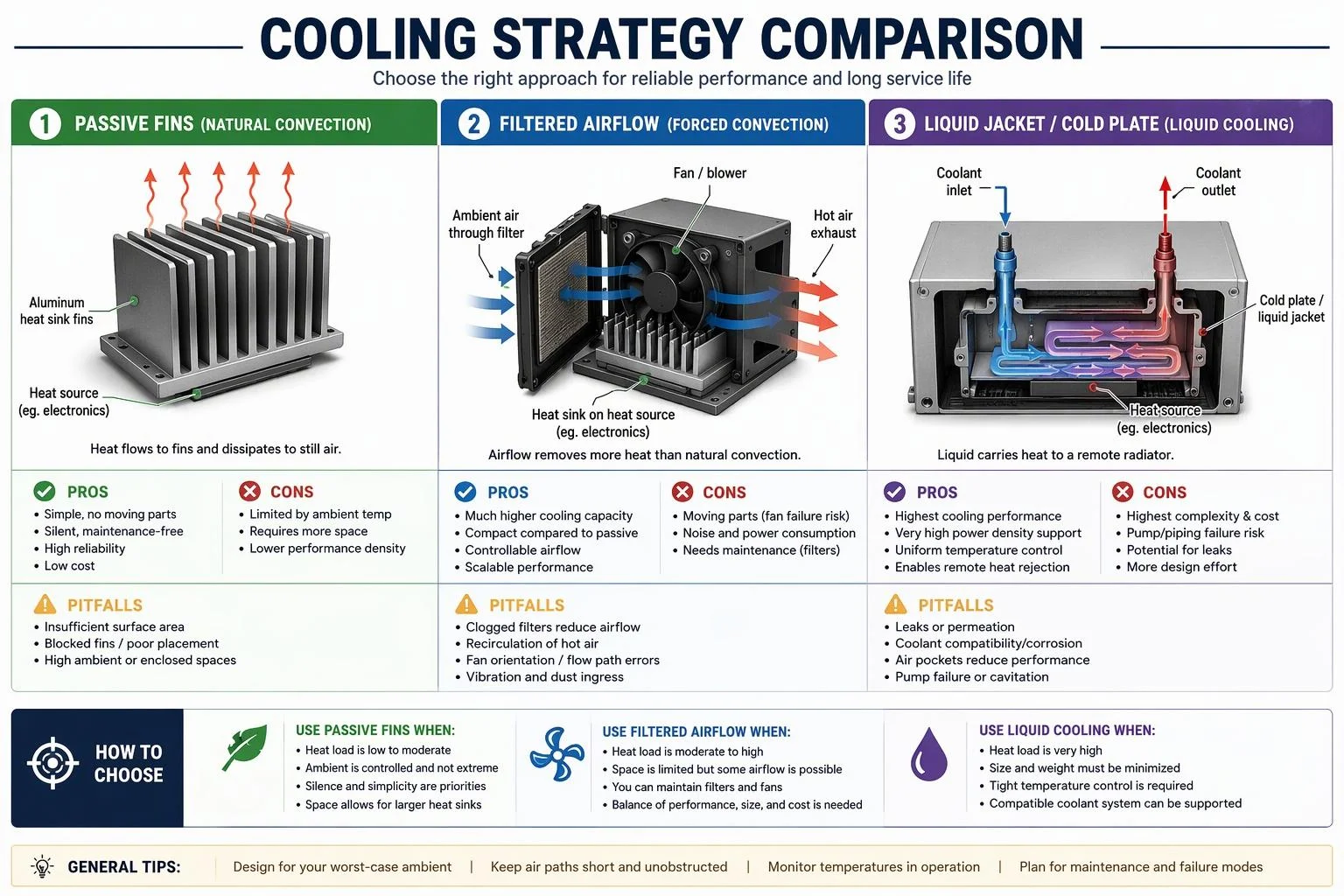
Cooling choice follows from the loss budget and the enclosure, not from preference. A high current slip ring in a ventilated machinery house can usually run passively with adequate ring area and spacing; the same ring sealed to IP65 in a marine pedestal needs either a larger thermal mass, a forced-air path with filtration, or a liquid circuit. Decide the cooling concept only after the total loss figure and the worst-case ambient are fixed, because retrofitting airflow into a sealed housing usually means changing the housing.
Passive, forced-air, and liquid cooling
Passive cooling is the default for open or well-ventilated installations. Its capacity comes from ring and housing surface area, so it rewards generous ring width, spacing between rings and a housing that conducts heat outward rather than trapping it. It has no moving parts and nothing to maintain, which matters on a crane where access is a platform and a permit.
Forced air raises capacity substantially but introduces a filter, a fan and a failure mode. Filter loading reduces flow over time, so the thermal margin you validated on day one is not the margin in month eighteen. Where the enclosure must stay closed, an internal circulation fan plus an air-to-air heat exchanger keeps contaminated site air out of the brush compartment while still moving heat to the housing.
Liquid cooling suits the highest current densities and the tightest envelopes, and it is the option most often paired with marine and offshore installations where ambient air is humid and saline. It adds a coolant loop, a pump or ship's supply connection, leak risk and a maintenance schedule. Whichever route you choose, validate it at the worst-case combination of ambient temperature, current and speed, not at nominal conditions.
Strategy | Typical fit | Main pitfall |
|---|---|---|
Passive (fins, surface area) | Ventilated machinery houses, moderate current | Underestimating enclosed-housing heat retention |
Forced air with filtration | Sealed pedestals needing IP protection | Filter loading eroding thermal margin |
Liquid jacket or loop | Highest currents, marine, tight envelopes | Leak paths and coolant maintenance |
Sealing, IP, and contamination control
Sealing protects the contact system, but it also removes the airflow that was carrying heat away, so IP rating and cooling strategy must be decided together. A higher IP rating is not automatically better; it is a trade of contamination resistance against thermal capacity.
Contamination control is where most field failures originate. Mersen identifies oil and hydrocarbon ingress, from bearing leaks, splashes carried by ventilation, or vapour condensing at hot points, as a cause of brushes sticking in their holders and of thick insulating films building on ring surfaces (Mersen carbon brush catalogue). The same source notes that the contact film forms best at an absolute humidity of roughly 8 to 15 g/m³ and becomes critical below about 2 g/m³, which is relevant to heated enclosures, dry-gas-filled housings and cold-climate installations. Sealing strategy should therefore address oil exclusion, humidity retention and dust ingress as three separate requirements rather than one IP number.
Vibration, shock, and mechanical integrity
Vibration degrades the brush-to-ring contact before it breaks anything, and the resulting arcing damages both surfaces. Mersen attributes contact deterioration to poor machine balancing, defective bearings, incorrect alignment and rings in poor condition, and recommends higher spring pressure for machines subject to shocks and vibration, citing a range of 350 to 500 g/cm² for heavily vibrating machines against 180 to 250 g/cm² for stationary machines (Mersen carbon brush catalogue).
Mechanical integrity checks for a high current slip ring on mobile or marine equipment should cover brush-holder clearance, so brushes neither stick nor rattle, terminal and shunt support against fatigue, bearing and seal loading, and mounting stiffness relative to the machine frame. Where the slip ring is mounted on a slewing ring or winch drum, confirm that frame deflection under load does not translate into ring run-out.
Monitoring, compliance, and validation
Monitoring turns a thermal design into a managed one. Instrument the prototype to find the real hotspots, then carry forward only the sensors that give early warning of the failure modes you cannot design out: brush wear, current imbalance and abnormal temperature rise. Validation then confirms the design at thermal equilibrium under worst-case current, speed and ambient, and demonstrates that parallel paths share current within an acceptable band.
Instrumentation and protection logic
A practical instrumentation set for a high current slip ring includes thermocouples or resistance sensors on the hottest ring and on the brush terminal block, a current transducer per parallel path where sharing is critical, and a wear or position indicator on at least one representative brush per ring. Speed and coolant flow, where liquid cooling is used, complete the picture.
Protection logic should act on rate of change as well as absolute level. A slow upward drift in ring temperature at constant load points to filter loading, coolant degradation or rising contact resistance, and is worth an alarm long before a trip. Current imbalance between parallel brushes is the earliest indicator of the self-reinforcing sharing problem, so set the alarm on deviation from the mean rather than on total current.
UK/EU standards and marine context
Compliance for a slip ring assembly is usually inherited from the machine it is fitted to, so the OEM engineer needs to know which standards the machine's technical file will cite. IEC 60204-1 covers the electrical equipment of machines and sets requirements for protective bonding, overcurrent protection and technical documentation (IEC 60204-1:2016+A1:2021). Marine installations fall under the IEC 60092 series for electrical installations in ships (IEC 60092 series), and classification societies such as Bureau Veritas issue type approvals for maritime slip rings.
Two regulatory dates matter for UK and EU OEMs. The EU Machinery Regulation (EU) 2023/1230 replaces the Machinery Directive 2006/42/EC from 20 January 2027, and brings digital documentation, software update logging and revised conformity assessment routes into scope (IES summary of Regulation (EU) 2023/1230). UKCA marking remains the route for the Great Britain market. Insulation coordination should follow the thermal class of the materials used; IEC 60085 sets out how insulation materials are classified by thermal endurance, and its classification of a material cannot be transferred to a system containing it without proof (IEC 60085).
Test to thermal equilibrium and current sharing
Thermal equilibrium has a defined meaning, and using it makes test reports comparable. IEC 60034-1 defines thermal equilibrium as the state where the temperature rise of the machine parts does not vary by more than 2 K per hour, determinable from a time–temperature plot where successive intervals show gradients below that figure (IEC 60034-1). Run until that criterion is met, not until the reading looks stable.
A validation sequence that answers the questions a technical file will ask:
Baseline at rated current, rated speed and declared maximum ambient; record all thermocouple channels to equilibrium.
Worst-case current at minimum speed, since low speed reduces both windage cooling and film quality.
Maximum speed at rated current, to capture friction and windage heating.
Current-sharing test: measure per-brush or per-path current at steady state and record the spread against the mean.
Intermittent duty replication, if the machine's duty cycle includes repeated starts or reversing loads.
Record the ambient, the coolant temperature and the measurement method alongside every result, because a temperature rise figure without its reference coolant temperature cannot be compared with a limit.
Conclusion
High current slip ring design succeeds when the electrical and thermal calculations are treated as one problem. Size the ring for the duty cycle rather than the nameplate current, set a temperature rise limit that leaves real margin against the insulation class, and remember that contact losses, friction and windage all end up in the same thermal path. The most common pitfalls are predictable: sizing on average current instead of worst-case peak, assuming parallel brushes share equally, sealing a housing without replacing the cooling capacity the seal removed, and validating at nominal ambient rather than at the hottest day the machine will see.
The next steps are sequential. Build or specify a prototype with instrumentation designed in, not added afterwards. Run it to thermal equilibrium at the worst-case combination of current, speed and ambient, and record current sharing across parallel paths at the same time. Then document the result in a form that supports CE or UKCA marking: the loss calculation, the thermal test report with its ambient reference, the instrumentation and protection schedule, and the maintenance intervals for brushes, filters and coolant.
Lifecycle support deserves a place in that documentation from the start. Brush wear rate, filter change interval and coolant service schedule all depend on duty, so state the assumptions explicitly and give the operator a way to check them in service. A slip ring that is correctly sized, honestly validated and properly documented is a maintenance item; one that is not becomes an unplanned outage.
[Brand insertion guidance]
Where a standard high current slip ring cannot meet the thermal or environmental envelope, custom engineering is the appropriate route, and that is where JINPAT's experience is relevant. JINPAT has designed and manufactured slip rings since 1996, and its high current integrated range is specified for up to 4000 A per ring, with current capacity, circuit configuration, rotational speed, operating temperature and protection level all customizable (JINPAT high current integrated slip rings). For offshore work, JINPAT has published a high current slip ring for offshore cranes rated at up to 800 A per channel with an integrated thermal management system and a corrosion-resistant housing (JINPAT offshore crane slip ring), and a more recent offshore lifting design combining high current transmission with a large through bore and improved maintenance access (JINPAT offshore high current slip ring announcement).
Those figures are product-specific and should be confirmed against the current datasheet for your application rather than assumed as a general capability. JINPAT holds ISO 9001 and ISO 14001 certification, CE marking for its LPTS series through-bore slip rings, RoHS 2.0 compliance and a Bureau Veritas marine type approval for maritime slip rings (JINPAT quality and certifications). For an OEM engineer preparing a technical file, the useful next step is to bring the duty cycle, ambient envelope, IP requirement and mounting constraints to a technical review, so the thermal and contact design can be matched to the machine rather than to a catalogue envelope. If your application sits comfortably within a standard range, a standard unit remains the lower-risk choice; custom engineering is justified when measured requirements exceed what the standard platform can deliver.

